Research Article | | Peer-Reviewed

Study on Electromagnetic Environmental Impact of AC Overhead Transmission Lines with Different Erection Methods

Received: 17 November 2025     Accepted: 1 December 2025     Published: 24 December 2025
Views:       Downloads:
Abstract

This study investigates the electromagnetic environmental impact of AC overhead transmission lines with different erection methods, focusing on power frequency electric field (measured by electric field intensity) and power frequency magnetic field (characterized by magnetic induction intensity). Based on the equivalent charge theory, simulations and calculations were conducted using the Matlab Radiation Calculate platform, analyzing the effects of line-to-ground distance, erection mode, conductor layout, and phase sequence arrangement on the electromagnetic field. For single-circuit lines, the inverted triangle (compact) layout exhibits more concentrated field intensity distribution and a smaller high-field-strength area compared to equilateral triangle and horizontal layouts. For double-circuit or multi-circuit lines on the same tower, reverse phase sequence arrangement effectively reduces both power frequency electric field intensity (maximum 2355 V/m vs. 3178 V/m for in-phase sequence) and magnetic induction intensity (4.137 μT vs. 6.601 μT for in-phase sequence). Increasing the line-to-ground height significantly decreases the maximum power frequency electric field intensity (reducing by 0.4–1.6 kV/m per 1m height increase), while its impact on magnetic induction intensity is linearly slight. All calculated values comply with GB8702-2014 standards (electric field ≤4000 V/m, magnetic induction ≤100 μT for public exposure). The power frequency electric field intensity is identified as the key electromagnetic environmental factor requiring attention. This study provides a theoretical basis for optimizing transmission line erection to mitigate electromagnetic environmental impacts.

Published in American Journal of Electrical Power and Energy Systems (Volume 14, Issue 6)
DOI 10.11648/j.epes.20251406.11
Page(s) 110-119
Creative Commons

This is an Open Access article, distributed under the terms of the Creative Commons Attribution 4.0 International License (http://creativecommons.org/licenses/by/4.0/), which permits unrestricted use, distribution and reproduction in any medium or format, provided the original work is properly cited.

Copyright

Copyright © The Author(s), 2025. Published by Science Publishing Group

Keywords

Transmission Line, Electromagnetic Radiation, Environmental Impact

1. Introduction
The working frequency of China's AC power grid is 50Hz, so the frequency is called "industrial frequency" in the power field, referred to as "power frequency", and the resulting electric field and magnetic field are called power frequency electric field and power frequency magnetic field. The power frequency electric field is described by the electric field intensity, and the power frequency magnetic field is described by the magnetic induction intensity.
When a voltage is applied to a transmission line or equipment, the charged conductor carries an electric charge, which creates an electric field around the conductor. If the voltage applied to the conductor is a power frequency alternating voltage, the conductor carries a low-frequency alternating charge, and at the same time, a low-frequency electric field is formed in the space between the conductor and the earth , that is, a power frequency electric field. Electric field strength is measured as the difference in voltage per unit distance along a direction ("voltage") and is measured in volts or kilovolts per meter (V/m or kV/m).
When there is power frequency current flowing in the transmission line or equipment, the power frequency magnetic field is induced around the current-carrying conductor, and the physical quantity representing its magnetic field capacity is called magnetic field intensity H, with A/m as the unit of measurement. The corresponding magnetic induction B produced by the same magnetic field intensity in the surrounding space depends on the permeability of the medium in the surrounding space. For air, the permeability μ o is constant, μ o = 4π × 10 -7 Wb/ (A. M). The legal measurement unit of magnetic induction intensity is Tesla (T), which is generally measured by mT or μT in the environment of human body (1 T = 10 3 mT = 10 6 μT).
The electromagnetic environmental problems caused by AC overhead transmission lines are mainly the influence of power frequency electric field and power frequency magnetic field, and the size of power frequency electromagnetic field is affected by the height of the line conductor, the arrangement of the conductor (layout, phase sequence) and so on .
The equivalent charge method, also known as the simulated charge method, is one of the main methods for numerical calculation of electrostatic fields . Similar to the mirror method , the simulated charge method is based on the uniqueness theorem of electrostatic fields . It replaces the continuous distribution of free charges on the surface of the conductor electrode with a set of discrete charges located inside the conductor (such as a set of point charges, line charges, or ring charges set inside the conductor ). These discrete charges are called simulated charges, and then using the superposition theorem, the analytical formulas of these simulated charges are applied to calculate the potential or electric field strength at any point in the field. These simulated charges are determined based on the boundary conditions of the field. The essence of simulating charging methods is to find and determine the simulated charge . By combining this theory with software prediction, the magnitude of the electromagnetic field impact on high-voltage AC transmission lines can be clearly and quantitatively determined.
The Matlab Radiation Calculate electromagnetic radiation calculation platform is a calculation model developed based on the above theories of electric and magnetic fields . MATLAB is developed and launched by Mathworks in the United States for matrix numerical calculations and has powerful graphics processing capabilities. It integrates various practical functions in daily mathematical processing, including efficient matrix operations, numerical operations, graphics generation, and signal processing. It is currently one of the main software tools used for numerical operations and simulation, with very powerful functions.
After considering various numerical calculation algorithms for the electric field of transmission lines, this study chooses the simulated charge method recommended by the International Conference on Large scale Electric Grids Working Group 36.01, and uses MATLAB to write a simulation calculation program for the power frequency electric field based on the simulated charge method. The distribution law of the electric field of the line under different conditions and the factors affecting its distribution are analyzed and studied, which provides certain reference significance for the optimization of the electromagnetic environment and the construction of transmission lines.
In order to explore the electromagnetic environment impact of AC overhead transmission lines and the prevention and response of environmental disputes caused by it , the following work has been done in this paper: Through the equivalent charge theory , the power frequency electromagnetic field around the transmission line is simulated and calculated by Matlab Radiation Calculate platform. The influence of power frequency electromagnetic field under the conditions of different line ground distance, different erection mode and different conductor layout mode of single circuit line is mainly calculated, and the basic law of electromagnetic environment influence of AC overhead transmission line is obtained .
2. Calculation and Analysis of Influence of Different Erection Mode on Electromagnetic Field
Due to different requirements in design, construction and other aspects, AC overhead transmission lines have different erection methods, which will bring different electromagnetic environment impacts. This chapter studies the impact of common transmission line erection methods on electromagnetic field distribution in actual construction.
2.1. Calculation and Analysis of the Impact of Single-Circuit and Double-Circuit Erection on the Electromagnetic Environment
A typical 220kV line is selected for calculation below. See Table 1 and Table 2 for relevant parameters of erection. The electromagnetic environment impact of single-circuit erection, double-circuit erection and four-circuit erection of the line is simulated and calculated respectively by selecting a height of 12m to the ground. Meanwhile, the electromagnetic environment impact of different phase sequence arrangement modes is considered respectively when calculating the double-circuit and four-circuit erection on the same tower . See Fig. 1 for the selected tower type.
Table 1. List of Line Calculation Parameters.

Line type

Single-circuit line

Double-circuit line

Conductor model

2×JL/G1A-300/25

2×JL/G1A-400/35

Minimum outer diameter of single conductor (mm)

23.76

26.82

Splitting number

2

2

Current carrying capacity (A)

345

460

Bundle conductor spacing (mm)

400

400

Type of tower

2A5-J1

2E5-SDJ

Table 2. Phase Sequence Arrangement Parameters of 220kV Transmission Line.

Phase sequence arrangement

Single-circuit line

Double-circuit line

Triangular arrangement

——

In-phase sequence

——

A1 A2

B1 B2

C1 C2

Reverse phase sequence

——

A1 C2

B1 B2

C1 A2

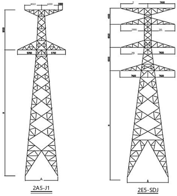
Figure 1. Calculation Tower Diagram.
Figure 2 shows the calculation results of power frequency electric field intensity of lines with different erection methods. It can be seen from the figure that the transmission line of each erection mode has a distance value with obviously higher power frequency electric field intensity, and shows a lower power frequency electric field value at other distance positions.
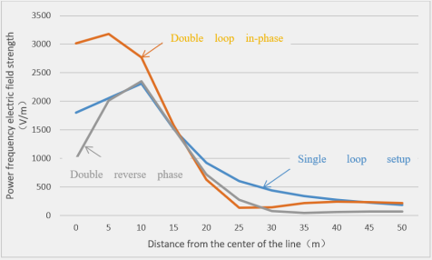
Figure 2. Calculation Results of Power Frequency Electric Field Intensity of Lines with Different Erection Methods.
It can be seen from Figure 2 that the maximum power frequency electric field intensity is 3178 V/m for the same phase sequence erection and 2355 V/m for the reverse phase sequence erection in the double-circuit erection of the same tower. Similarly, in the case of double-circuit erection, when the conductors are arranged in reverse phase sequence, the power frequency electric field intensity under the line is relatively small, and the maximum field intensity under the line is also the smallest. Therefore, the reverse phase sequence arrangement should be adopted when the double-circuit transmission line is adopted, which can effectively reduce the power frequency electric field intensity under the line.
Figure 3 shows the calculation results of power frequency magnetic induction intensity of lines with different erection methods. It can be seen from the figure that the transmission line of each erection mode generally shows that the greater the distance from the center, the smaller the power frequency magnetic induction intensity.
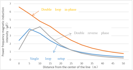
Figure 3. Calculation Results of Power Frequency Magnetic Induction Intensity of Lines with Different Erection Methods.
It can be seen from Figure 3 that the maximum power frequency magnetic induction intensity is 6.601 μT for the same phase sequence erection and 4.137 μT for the reverse phase sequence erection in the double-circuit erection of the same tower type. Similarly, in case of double-circuit erection or four-circuit erection, when the conductor is arranged in reverse phase sequence, the power frequency magnetic induction intensity under the line is relatively small , and the magnetic induction field intensity under the line is also the smallest. The maximum value of power frequency magnetic induction intensity of different erection methods is in the range of 4. 137 μT ~ 8.554 μT, and there is a large margin from the limit value of power frequency magnetic induction intensity of 100 μT, so the power frequency magnetic induction intensity is not the key factor to determine the best erection method of the line.
2.2. Calculation and Analysis of the Influence of Single-Circuit Line Conductor Layout on Electromagnetic Field
The conductor layout of single circuit transmission line may affect the electromagnetic environment of the line. At present, taking the 1000 kV single-circuit line as an example, there are three different ways of conductor arrangement : horizontal arrangement, regular triangle and inverted triangle (compact). The following is the prediction and calculation of UHV (Ultra-High Voltage) AC lines with three arrangement modes for the tower type in Figure 4.
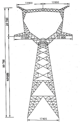
Figure 4. Type of 1000 kV AC Line Triangular Arrangement Cathead Tower.
To facilitate comparison, the following calculation conditions are set:
(1) The voltage level is set to 1000 kV.
(2) 8 × LGJ-630/45 shall be uniformly used as the conductor of high-voltage power transmission line, the outer diameter of the conductor shall be 3.36 cm, and the split spacing shall be 40.0 cm.
(3) The phase-to-phase distance of equilateral triangle and inverted triangle high-voltage transmission lines is set to 31.2m with reference to the phase-to-phase distance of 1000 kV triangular arrangement cathead tower shown in Figure 4.
(4) The distance between the transmission line and the ground is uniformly set as 23 m. The relationship between the calculated power frequency electric field intensity, power frequency magnetic induction intensity and the three arrangements is shown in Figure 5 and Figure 6.
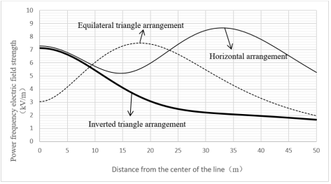
Figure 5. Power frequency electric field intensity under three arrangement modes of single circuit.
It can be seen from Figure 5 that the distribution range of field intensity is more concentrated and the distribution range of high field intensity area is smaller in the inverted triangle arrangement than in the regular triangle arrangement and horizontal arrangement. For the horizontal alignment, the electric field distribution shows an obvious saddle shape, with the largest coverage in the high field strength region, and the inverted triangular (compact) alignment has the smallest maximum field strength below the line and the high field strength coverage region.
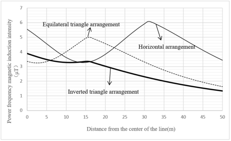
Figure 6. Power frequency magnetic induction intensity under three arrangement modes of single circuit.
It can be seen from Figure 6 that the peak value of the magnetic field intensity under the line is smaller in the inverted triangle arrangement than in the regular triangle arrangement and horizontal arrangement. When the phase conductors are horizontally arranged, the magnetic induction intensity is the largest, and the range of high magnetic field is the widest.
Based on the distribution of electric field and magnetic field, it can be seen that the inverted triangle (compact) line can effectively reduce the power frequency electromagnetic field under the line, which has obvious advantages.
2.3. Calculation and Analysis of the Influence of Line Erection Height on Electromagnetic Field
The minimum distance between transmission line and ground directly affects the electromagnetic environment level of transmission line . In the following, the single-circuit line of the UHV AC demonstration project in China is selected for prediction and calculation. In order to facilitate comparison, the calculation conditions are set as follows:
1) The voltage level is 1000 kV; 2) The conductor of high-voltage power transmission line is 8 × LGJ-630/45, the outer diameter of the conductor is 3.36 cm, and the split spacing is 40.0 cm; 3) See Figure 7 for tower type calculation.
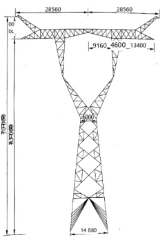
Figure 7. Tower Type Diagram of 1000 kV AC Line.
Figure 8 shows the relationship between the line erection height and the power frequency electric field intensity. The curve from top to bottom is the line height of 21m to 40m. It can be seen from the figure that the power frequency electric field intensity decreases with the increase of the line erection height; Combined with the tower type, the maximum electric field intensity at each erection height appears at about 3m outside the side-phase conductor. Since the tower type selected in this study is horizontal arrangement of three-phase line, the power frequency electric field intensity in Figure 8 first decreases with the increase of distance from the line center (the middle phase conductor), and then gradually increases with the approach to the side phase conductor.
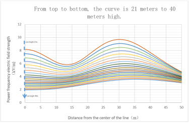
Figure 8. Relationship between line erection height and power frequency electric field intensity.
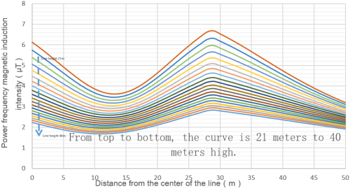
Figure 9. Relationship between line erection height and power frequency magnetic induction intensity.
Figure 9 shows the relationship ‘between the line erection height and the power frequency magnetic induction intensity. The curve from top to bottom is the line height of 21m to 40m. It can be seen from the figure that with the increase of the line erection height, the power frequency electric field intensity decreases, but the overall change range is not large.
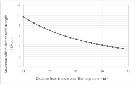
Figure 10. Relationship between Maximum Electric Field Intensity under Line and Line Erection Height.
Figure 10 shows the relationship between the maximum electric field intensity under the line and the overhead height of the line. It can be seen that the maximum value of the power frequency electric field intensity under the line decreases with the increase of the distance between the transmission line and the ground, and the range is relatively obvious. When the distance between the transmission line and the ground increases by 1m, the maximum value of the power frequency electric field intensity under the line decreases by 0. 4 ~ 1. 6 kV/m. Therefore, by increasing the distance between the transmission line and the ground, the power frequency electric field intensity can be effectively reduced to meet the ground field intensity limit standard.
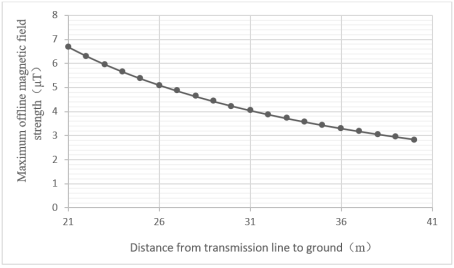
Figure 11. Relationship between Maximum Magnetic Induction Intensity under Line and Line Erection Height.
Figure 11 shows the relationship between the maximum magnetic induction intensity under the line and the height of the line. It can be seen from the figure that with the increase of the distance between the transmission line and the ground, the maximum magnetic field under the line will decay linearly, but the overall change range is not large. Therefore, the influence of the distance between the transmission line and the ground on the power frequency electric field of the transmission line is more obvious.
3. Conclusion
In order to understand the electromagnetic environment impact of different installation methods of transmission lines, this study conducted simulation calculations on typical inverted triangle (compact) arranged single circuit overhead lines, horizontally arranged single circuit overhead lines, double circuit same phase sequence overhead lines, double circuit reverse phase sequence overhead transmission lines, and different installation heights of the same transmission line. The following conclusions are drawn:
1. As the distance between the measuring point and the center of the line increases, both the power frequency electric field intensity and the power frequency magnetic induction intensity show a trend of first increasing and then decreasing, reaching their peak at the edge phase conductor.
2. The arrangement of single circuit wires can have an impact on the power frequency electromagnetic field. For single circuit lines, the distribution of field strength is more concentrated in the inverted triangle (compact) arrangement compared to the regular triangle arrangement and horizontal arrangement, and the range of high field strength distribution is smaller.
3. The phase sequence arrangement of the wires in the line will have an impact on the power frequency electromagnetic field. For double or multiple circuit lines on the same tower, using reverse phase sequence arrangement not only reduces the offline power frequency electric field strength compared to same phase sequence and out of phase sequence, but also minimizes the maximum field strength below the line.
4. The height of transmission lines above ground will have an impact on the power frequency electromagnetic field. Increasing the height of the line to ground can significantly reduce the intensity of the offline power frequency electric field, but when it reaches a certain height, the growth trend gradually decays. As the height of the transmission line to the ground increases, the maximum magnetic field offline decreases linearly, but the overall change amplitude is relatively small. Therefore, the influence of the distance of the transmission line to the ground on the power frequency electric field is more significant.
5. The power frequency electric field strength and power frequency magnetic induction strength at all measuring points of the lines calculated this time are all less than the public exposure control limit requirements of 4000V/m for electric field strength and 100 μ T for magnetic induction strength corresponding to a frequency of 50Hz in the "Electromagnetic Environment Control Limits" (GB8702-2014). At the same time, the power frequency electric field strength of farmland, gardens, grasslands, poultry and livestock breeding areas, aquaculture water surfaces, roads and other places meets the limit requirement of 10kV/m. And the measured value of power frequency magnetic induction intensity is much lower than the national standard, so the electric field strength is a more important electromagnetic environmental impact that needs to be paid attention to.
Abbreviations

AC

Alternating Current

UHV

Ultra-High Voltage

Author Contributions
Han Chen is the sole author. The author read and approved the final manuscript.
Conflicts of Interest
The author declares no conflicts of interest.
References
[1] Zhang Yong, Vivien Leigh Analysis of the Impact of High Voltage Transmission Lines on Induced Polarization and Magnetic Methods [J]. Resources, Environment and Engineering, 2020, 34 (03): 453-457.
[2] S Yu Perov, O V Belaya, T A Khrennikova. Experimental and theoretical assessment of power frequency electric field individual protective means [J]. IOP Conference Series: Materials Science and Engineering, 2019, 487(1): 12-17.
[3] Zhang Jingwen, Wu Jing, Xie Tianyu. Study on Harmonic Radiation Phenomena Related to Near-Earth Space and Power Grid [J]. Transactions of China Electrotechnical Society, 2023, 38(11): 2689-2698.
[4] Zhao Hua, Chen Xiaoyu, Yang Qing. Audible Noise and Electric Field Distribution Characteristics of 750kV AC Lines in High-Altitude Areas [J]. Transactions of China Electrotechnical Society, 2024, 39(5): 1120-1129.
[5] Li Jing, Wang Lei, Zhao Jun. Calculation and Measured Analysis of Electromagnetic Environment for 110kV Transmission Lines [J]. Electrical Engineering, 2025, (1): 173-179.
[6] Wang Hao, Li Gang, Liu Zehong, et al. Optimization and Measured Verification of Electromagnetic Environment for 1000kV UHV AC Transmission Lines [J]. High Voltage Engineering, 2024, 50(3): 987-995.
[7] Zhao H, Li C, Chen G. Optimization of Electromagnetic Environment for UHV AC Transmission Lines Based on Improved Genetic Algorithm [J]. IEEE Access, 2024, 12: 45678-45689.
[8] Liu Zhijian MATLAB Application Programming Interface User Guide [M]. Beijing: Science Press, 2001.
[9] Science and Technology Department of State Grid Corporation of China Communication Manual for Typical Environmental Issues in Power Transmission and Transformation [M]. Beijing: China Electric Power Press, 2016: 25-26.
[10] Xiao Dongping, He Wei, Yang Fan, etc Calculation and span selection of power frequency electric field for ultra-high voltage transmission lines under different meteorological conditions [J]. High Voltage Technology, 2009, 35 (09): 2081-2086.
[11] Jia Chuanzhao, Qiang Jing Theoretical Calculation and Testing Analysis of Electromagnetic Environmental Impact of AC Overhead Transmission Lines [J]. Science and Technology Perspective, 2019, 263 (05): 89-93.
[12] Deng Weini, Liu Yanjun Development and Application of Electromagnetic Environment Impact Prediction Software for AC Transmission Lines [J]. Shandong Industrial Technology, 2016, 000 (014): 178-178179.
[13] Chen Er, Zhang Ying, Cai Xuan, etc Design of an Electromagnetic Environment Impact Prediction and Calculation Program for High Voltage AC Overhead Transmission Lines [J]. Hubei Electric Power, 2016, 40 (05): 29-34.
[14] Chen Xi, Zhou Chao, Ma Yutang. Electromagnetic Environment Characteristics of 500kV Double-Circuit on the Same Tower Flexible Compact AC Transmission Lines [J]. Power System Technology, 2023, 47(7): 2612-2620.
[15] Liu Yang. Study on Optimal Design of Electromagnetic Environment for Flexible Compact AC Transmission Lines [D]. Xi'an: Xi'an Jiaotong University, 2023.
[16] Zou Anxin, Xu Luwen Simulation analysis and research on the influence of phase sequence on the power frequency electromagnetic field of ultra-high voltage AC transmission lines [J]. High Voltage Apparatus, 2015 (03): 88-93.
[17] Ultra-high Voltage AC/DC Power Transmission, Springer Science and Business Media LLC, 2018.
Cite This Article
  • APA Style

    Chen, H. (2025). Study on Electromagnetic Environmental Impact of AC Overhead Transmission Lines with Different Erection Methods. American Journal of Electrical Power and Energy Systems, 14(6), 110-119. https://doi.org/10.11648/j.epes.20251406.11

    Copy | Download

    ACS Style

    Chen, H. Study on Electromagnetic Environmental Impact of AC Overhead Transmission Lines with Different Erection Methods. Am. J. Electr. Power Energy Syst. 2025, 14(6), 110-119. doi: 10.11648/j.epes.20251406.11

    Copy | Download

    AMA Style

    Chen H. Study on Electromagnetic Environmental Impact of AC Overhead Transmission Lines with Different Erection Methods. Am J Electr Power Energy Syst. 2025;14(6):110-119. doi: 10.11648/j.epes.20251406.11

    Copy | Download

  • @article{10.11648/j.epes.20251406.11,
      author = {Han Chen},
      title = {Study on Electromagnetic Environmental Impact of AC Overhead Transmission Lines with Different Erection Methods},
      journal = {American Journal of Electrical Power and Energy Systems},
      volume = {14},
      number = {6},
      pages = {110-119},
      doi = {10.11648/j.epes.20251406.11},
      url = {https://doi.org/10.11648/j.epes.20251406.11},
      eprint = {https://article.sciencepublishinggroup.com/pdf/10.11648.j.epes.20251406.11},
      abstract = {This study investigates the electromagnetic environmental impact of AC overhead transmission lines with different erection methods, focusing on power frequency electric field (measured by electric field intensity) and power frequency magnetic field (characterized by magnetic induction intensity). Based on the equivalent charge theory, simulations and calculations were conducted using the Matlab Radiation Calculate platform, analyzing the effects of line-to-ground distance, erection mode, conductor layout, and phase sequence arrangement on the electromagnetic field. For single-circuit lines, the inverted triangle (compact) layout exhibits more concentrated field intensity distribution and a smaller high-field-strength area compared to equilateral triangle and horizontal layouts. For double-circuit or multi-circuit lines on the same tower, reverse phase sequence arrangement effectively reduces both power frequency electric field intensity (maximum 2355 V/m vs. 3178 V/m for in-phase sequence) and magnetic induction intensity (4.137 μT vs. 6.601 μT for in-phase sequence). Increasing the line-to-ground height significantly decreases the maximum power frequency electric field intensity (reducing by 0.4–1.6 kV/m per 1m height increase), while its impact on magnetic induction intensity is linearly slight. All calculated values comply with GB8702-2014 standards (electric field ≤4000 V/m, magnetic induction ≤100 μT for public exposure). The power frequency electric field intensity is identified as the key electromagnetic environmental factor requiring attention. This study provides a theoretical basis for optimizing transmission line erection to mitigate electromagnetic environmental impacts.},
     year = {2025}
    }
    

    Copy | Download

  • TY  - JOUR
    T1  - Study on Electromagnetic Environmental Impact of AC Overhead Transmission Lines with Different Erection Methods
    AU  - Han Chen
    Y1  - 2025/12/24
    PY  - 2025
    N1  - https://doi.org/10.11648/j.epes.20251406.11
    DO  - 10.11648/j.epes.20251406.11
    T2  - American Journal of Electrical Power and Energy Systems
    JF  - American Journal of Electrical Power and Energy Systems
    JO  - American Journal of Electrical Power and Energy Systems
    SP  - 110
    EP  - 119
    PB  - Science Publishing Group
    SN  - 2326-9200
    UR  - https://doi.org/10.11648/j.epes.20251406.11
    AB  - This study investigates the electromagnetic environmental impact of AC overhead transmission lines with different erection methods, focusing on power frequency electric field (measured by electric field intensity) and power frequency magnetic field (characterized by magnetic induction intensity). Based on the equivalent charge theory, simulations and calculations were conducted using the Matlab Radiation Calculate platform, analyzing the effects of line-to-ground distance, erection mode, conductor layout, and phase sequence arrangement on the electromagnetic field. For single-circuit lines, the inverted triangle (compact) layout exhibits more concentrated field intensity distribution and a smaller high-field-strength area compared to equilateral triangle and horizontal layouts. For double-circuit or multi-circuit lines on the same tower, reverse phase sequence arrangement effectively reduces both power frequency electric field intensity (maximum 2355 V/m vs. 3178 V/m for in-phase sequence) and magnetic induction intensity (4.137 μT vs. 6.601 μT for in-phase sequence). Increasing the line-to-ground height significantly decreases the maximum power frequency electric field intensity (reducing by 0.4–1.6 kV/m per 1m height increase), while its impact on magnetic induction intensity is linearly slight. All calculated values comply with GB8702-2014 standards (electric field ≤4000 V/m, magnetic induction ≤100 μT for public exposure). The power frequency electric field intensity is identified as the key electromagnetic environmental factor requiring attention. This study provides a theoretical basis for optimizing transmission line erection to mitigate electromagnetic environmental impacts.
    VL  - 14
    IS  - 6
    ER  - 

    Copy | Download

Author Information